
High-Speed Autonomous Line Follower Robot
Modular Dual-Board Architecture Designed in EasyEDA: 16-Channel IR Sensor Array, Custom ESP32 Controller, Dual H-Bridge Motor Drivers, and Onboard Battery Management.
16-Channel IR Array
Ultra-wide 16-channel phototransistor bar delivering high spatial resolution to track sharp bends, 90° corners, and line crossings without blind spots.
Dual-Board System
Modular architecture splitting the front sensor bar from the central controller to isolate high-frequency optical signals from inductive motor spikes.
Motor & Power Stage
High-current dual H-bridge motor drivers, flyback protection diodes, low-ESR bulk capacitors, and wide copper planes for aggressive acceleration.
OLED & Field Tuning
Integrated 0.96" OLED display and onboard tactile push buttons enable live field adjustment of PID constants (Kp, Ki, Kd) without computer connection.
9 High-Resolution Assets: Assembled Robot, EasyEDA Schematics, & Custom Controller PCB
Fully Assembled Autonomous Line Follower Robot
Complete racing-grade robot chassis integrating micro metal gearmotors, front-mounted 16-sensor array bar, custom ESP32 base controller, OLED, and LiPo power supply.
Autonomous line tracking at high velocities poses severe electrical challenges: inductive voltage spikes and EMF noise from rapid motor switching can corrupt sensitive analog IR sensor readings. To conquer this, the hardware was split into two dedicated custom PCBs designed in EasyEDA:
16-Channel IR Sensor Bar
Schematic features 16 matched IR emitter-receiver pairs mounted in an elongated linear geometry at the front bumper. Provides a continuous spatial gradient across a 150mm track span, resolving acute curves and sharp angled turns.
ESP32 Core & Power BMS
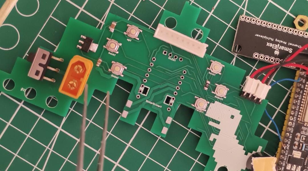
Schematic titled base board featuring the ESP32 microcontroller running dual-core FreeRTOS PID loops, onboard 3.3V buck step-down regulation, battery voltage divider for fuel-gauging, and tactile input buttons.
High-Current Trace Routing
Routed in EasyEDA with 40-mil power traces for dual H-bridge motor outputs, flyback suppression diodes, star ground return paths to eliminate ground bounce, and isolated signal routing for the I2C OLED display.
To maintain maximum forward velocity without oscillating off the track, the ESP32 executes a weighted average position algorithm across the 16 IR sensors:
Position = (∑ (Sensor[i] × Weight[i])) / (∑ Sensor[i]);
Error = Position - Target_Center;
// Differential PID Correction
Output = (Kp * Error) + (Ki * Integral) + (Kd * Derivative);
Left_Motor = Base_Speed + Output;
Right_Motor = Base_Speed - Output;
The Proportional term (Kp) responds instantly to line offset, the Derivative term (Kd) dampens overshoot on sharp entry into corners, and the Integral term (Ki) removes steady-state drift on sweeping turns.
Live Sensor Gradient & Motor Differential
Adjust the simulated track curve to see the 16-channel sensor array detect position and observe how the ESP32 computes differential motor speeds:
DC brushed gearmotors generate continuous high-frequency inductive flyback spikes during PWM switching. Without isolation, these transients can reset the ESP32 microcontroller or cause erratic ADC conversions.
Dedicated Dual Ground Planes
Analog optical ground and digital/motor high-current ground meet only at a single star point at the battery input.
Onboard Buck Regulation
Efficient DC-DC buck converter drops battery voltage (7.4V LiPo / 2S) down to an ultra-clean 3.3V rail with high ripple rejection.
Flyback Clamping
Fast Schottky diodes across motor terminals clamp reverse inductive spikes instantly.
Hardware Calibration Buttons
Tactile buttons connected to interrupt pins allow cycling through PID parameters and setting calibration offsets directly on the track.
EasyEDA (Dual 2-Layer Boards)
ESP32 Dual-Core 240MHz Core
16-Channel High-Density IR Bar
Dual H-Bridge High-Current Driver
Micro Metal Gearmotors (High-RPM)
0.96" I2C OLED (128x64)
High-Frequency PID (Weighted Average)
Tactile Push Buttons (On-Board Tuning)
LiPo Battery with Regulated BMS & Filtering
Star Ground & Isolated Motor Copper Pour
OLED Interface & Live Telemetry
The 0.96" SSD1306 I2C OLED display mounted directly on the controller board provides an interactive pit-stop dashboard: