
My First Custom PCB: 6-Dot Tactile Braille Controller
A custom-fabricated PCB driving a 6-dot tactile matrix with MOSFET thermal actuators and I2C LCD interface.
Fabricated PCB Board
Top and bottom copper routing with clean solder mask, ground plane, and silk screen labels.
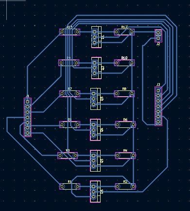
Fabricated PCB Board — Top & Bottom Copper Routing
Top and bottom copper routing with clean solder mask, full ground plane, and silk screen labels.
“Six months ago, I took a major step in my hardware journey by designing and manufacturing my very first Printed Circuit Board.”
As an ECE student, I’ve always leaned toward being a “practical implementer” — someone who loves taking theoretical circuit concepts and turning them into physical reality. Moving away from messy, high-impedance breadboard wiring to a clean, fabricated board was a massive shift in how I approach hardware design.
This specific PCB serves as the hardware foundation for a tactile Braille display. It controls a 6-dot matrix using thermal actuators driven by high-efficiency power MOSFETs, seamlessly translating digital incoming text into physical Braille characters through an Arduino microcontroller and an I2C LCD interface.
Modern Workflows & Firmware Co-Development
One of the biggest takeaways from this project was the power of modern iterative engineering. Without a traditional formal software background, I built the firmware and logic entirely by collaborating with modern AI tools. It proved to me that bringing complex electronic systems to life requires a deep intuitive grasp of hardware, schematic sanity, and the persistent drive to build.
Schematic Sanity & ERC/DRC
Rigorous KiCad electrical rule checks before sending Gerber packages to fabrication.
Firmware Logic Synthesis
Synthesizing state machine logic for ASCII to 6-dot Braille actuator truth tables.
Practical Physical Testing
Multi-meter verification of logic gate pulses and high-current ground plane stability.
Controller Live Logic State Machine
Type any letter (A-Z) or click the buttons below to test how the controller energizes the 6 MOSFET gates and translates digital text to tactile dots:
Standard 2x3 Braille Layout
Live Logic Channel Drivers:
2-Layer FR4
Top and bottom copper routing with clean solder mask, full ground plane, and silk screen labels.
6x Low-Rds MOSFETs
High-efficiency power MOSFETs switching thermal actuators for rapid dot actuation without gate driver loss.
I2C 16x2 LCD
Two-wire serial interface (SDA/SCL) presenting ASCII characters and driver telemetry simultaneously.
Arduino / ATmega328P
Translates incoming digital ASCII stream to 6-bit tactile dot matrix with sub-millisecond gate strobing.
5V Logic & High-Current Rail
Isolated ground plane and bypass capacitors ensure logic stability during simultaneous thermal actuator pulses.
KiCad PCB & Gerber Output
Engineered entirely in KiCad with schematic capture, custom footprint library, and certified manufacturing Gerbers.